AC and DC Dummy Load

I wanted a variable load for 24VAC that would go up to at least 12VA. Before I would connected power resistors in series but that gets troublesome when you want to change the load with a fine resolution. There are variable power resistors or rheostats but they are big and clumsy and from what I can tell expensive. So I decided to design a little variable AC load that would simulate a resistive load and that would also work with DC. After a bit of work and one board spin I came up with this:

AC Load


Load Circuit

It works like the standard DC load that you can find all over the web with an op-amp that drives an N-Channel MOSFET with a current sense resistor but on this one I added a P-Channel MOSFET in series. This way during the positive half of the AC waveform the body diode of the  P-Channel MOSFET conducts and the  N-Channel MOSFET provides the load and then during the neagtive half of the AC waveform the  the body diode of the  N-Channel MOSFET conducts and the  P-Channel MOSFET provides the load.

To turn of the MOSFETs the op-amp needs to drive the N-Channel FETs gate positive and the P-Channel FETs gate negative so I added a simple +/- 10V supply. First I bring in power through USB just because that is a simple and easy was to get 5V, also I thought I might redesign this with a micro-controller at some point that will be able to do more complex loads. The 5V is fed into a voltage doubling charge pump and then that is fed into an inverting charge pump.

When the voltage to be loaded is connected to the device it is divided by R1 and the potentiometer R3 which provides the set-point for the control loop this makes the load dependent on the voltage which means this simulates a resistive load unlike most DC loads which are constant current loads.

Op-AmpSupply


I had a few issues with this design to begin with:

  • First originally I had one gate resistor that was shared between both mosfets but I was getting some very high frequency oscillations when ever the N-Channel FET turned on, isolating the MOSFETs with separate gate resistors solved that issue.
  • Next I had trouble getting the control loop stable; originally I used the jellybean part TS321 for the op-amp but no matter what combination of gate drive resistor and compensation capacitor I couldn’t get it stable. I changed the op-amp to the fancier LM7321 which is a higher current output and unlimited capacitive load op-amp and with that I got the control loop stable.

One thing I would do if I do another revision of this design would be to add more protection. I have damaged it a few times by connecting the load power without connecting the 5V.

Full Schematic:

Variable AC-DC Load

Anyway this was a fun little project that I wanted to share :)

Andrew

Wifi Temperature Sensor Testing

Electric Imp CurrentLike I said in my last post I’ve decided to rethink my wireless temperature sensor. Instead of using a local wireless protocol like ZigBee or the Nordic Semiconductor 2.4GHz wireless. I want to investigate using WiFi instead. After doing a bit or research I found the Electric Imp WiFi modules (Electric Imp) look like they might be a good fit. They should have a low sleep current (<10uA) and seem to have a lot of support for the software side which is where I usually am lacking in my projects; I’m fine designing hardware but get frustrated with software development easy.

With some very quick back of the napkin calculations I figure that I can have one Electric Imp Running off 2 x AA batteries that logs the temperature and sends it out to the internet every hour and have it last at least a year on one set of batteries. Yesterday I bought and Electric Imp IMP001 module and a breakout board. I powered it with 2 x AA batteries in series and set it up to log the temperature of a thermistor and the battery voltage. With a  little bit of code I have it sending the readings out to Xively; I used them when they were called Cosm on a previous post.

Electric Imp Test

Here are the live feeds from Xivley for the past 24 hours for both the thermistor temperature and battery voltage (Sorry to all future readers if these go down eventually)

Now this isn’t a perfect test since the Wifi on the Electric Imp module with cut out when the voltage reaches 2.5V or about 1.25V per cell and Alkaline AA batteries are fully drained when they get to 0.8V per cell. So at some point I will need to design a board with a boot converter so I can utilize the full capacity of my batteries.

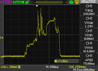
I did some testing last night to measure the current draw of the Imp module and found that my sleep current was a bit higher than what is specified in the datasheet; I was getting around 800uA but that’s most likely I have it setup wring and not going to sleep fully. I did make sure that I am controlling the thermistor properly which a GPIO pin so that isn’t wasting current when the device is asleep. I also measured the current when it wakes up and transmits.

Electric Imp Current


This was measured through a 10 ohm resistor so we have a peak current of about 130mA and an average current for the whole transmit pulse of about 50mA for 75ms. So that’s not bad as long as it’s not waking up very often I should get pretty decent battery life. I think when I have the whole thing setup I will probably have it text or e-mail me when the batteries get low.

Going forward on this project I think I am going to have to get another electric imp module so I can do some more development while I leave this one running and I will work on my own board with a boost converter and maybe some other sensors to connect to the Imp.

Andrew