Home Automation Project

A project I have have wanted to do for a while is a home automation system for my apartment so I finally think I am going to do it. I have a general idea of how it will work shown in the block diagram below:

I will have a bunch of wireless sensors scattered around my apartment that will gather data about temperature, light, occupancy…etc. These will probably use the Digi Xbee module I used on the quadcopter and will transmit their sensor readings back to a central server. I’m thinking right now I want these wireless modules to be battery powered so they are going to have to be very low power so that the batteries will last a long time. I think the first one I’m going to do will be a temperature sensor, but I will talk about that more on a later blog post.

I’m thinking I could do other wireless modules like maybe a light switch to turn on and off the lights. Some other ideas include modifying my room fans to be able to control them through my home automation network, and even connecting my coffee maker to it ;)

For the server right now I’m thinking of using an Arduino with an Ethernet shield and an Xbee module. Now I’m not the biggest Arduino fan but it makes a quick easy setup for a small lightweight server and gateway to my home network and the internet. The wireless modules will send sensor data to the Arduino which will post it to the web server. An alternative to the on board web server would be to use Cosm I haven’t looked into it too much but that could be an alternate place for the server to post the sensor data to. Possibly I will use the Arduino web server for a LAN web server to connect to when I am home and the Cosm server to view data when I am away from my apartment.

Anyway I have ordered an Arduino Ethernet shield and I will start by connecting a temperature sensor to it and working on setting up the sever portion before working on the wireless modules.

This should be a fun project. :)

PCB Buisness Card

Thought I would work on a new project over the Canada Day long weekend for a change of pace. I am going to make a PCB business card as something that I could show off at a job interview and things like that. I’ve decided to do a little circuit with the Microchip PIC10F208. This is a really neat little microcontroller; it comes in a tiny SOT23-6 package, with 0.75KB flash 24 Bytes of RAM, 1 x 8 Bit Timer, 1 Comparator. The best part is it’s cheap only $0.78 on Digikey for 1 chip. I could easily use a bigger microcontroller but sometimes it’s fun to have the challenge of a very limited microcontroller like this. If this goes well I might try doing more projects with it.

The Circuit

Microchip has a app note on how to do make a Capacitive touch button using two pins on it so I am going to try that and have the microcontroller blink a couple LEDs when it detects a touch. The circuit is very simple; the capacitive touch part is just a schottky diode, resistor and the capacitive sensing pad, a battery and two LEDs. The microcontroller pins can sink/source 25mA so I can easily drive an LED from these. I’m powering the whole thing with a 20mm coin cell battery since the mircocontroller is going to be sleeping most of the time so it should last a really long time.

Software

I haven’t programmed in assembly for a long time but the software should be real simple it will sleep most of the time and wake up one and a while to check the capacitive touch button like every 500ms or so and if it detects a touch it will blink the LEDs for a few seconds if it doesn’t detect a touch it will go back to sleep.

The PCB

Here’s a picture of the layout. It has the battery in the top right corner. The microcontroller/LED circuit in the top middle, the capacitive touch button on the bottom right, my name and contact info on the middle and a QR code leading back to my website on the bottom left. I am going to have it done with black silkscreen since I think that will look really nice and made with 0.8mm FR4 to make it a little thinner than normal and more business card like.I haven’t priced it all out but including the PCB the total BOM cost should come to around $7 which isn’t too bad most of the cost is from the connector batty and battery clip. I could use an SMT battery to save some cost but I would like it to be replaceable.

I’m going to send the Gerber files off to iTead Studio today and should hopefully get my PCBs back in a few weeks. Once I’ll blog about it once I get something up and running.

Schematic Here

Andrew

More Quadcopter Progress

I have been working on the quad copter some more and have made some more progress, although I sliced the tip of my finger open pretty good and broke one of the propellers in the process, but now the other axis id tuned fairly well. It doesn’t work as nice as the other axis right now though. It seems like one of the ESCs are stronger than the other, one of the motors runs significantly faster than the other as I mentioned in the previous post and I have narrowed it down to the ESC. Before I suspected it was the motor but swapped the two motors and the same side was stronger but after I swapped the ESCs the other motor was stronger. I have tried to calibrate out the difference to some success but it’d not perfect I may have to order a new ESC. Anyway here is a video of this axis working:

http://www.youtube.com/watch?v=VpuqQSjYKcY&feature=plcp

I still don’t have it flying though, I am going to have to work on that some more but that is enough for tonight.

Andrew

Quadcopter Progress

Well I have recived my new Lithium Polymer battery and have been working on my quadcopter some more. I have one axis tuned and working fairly well heres a cool Youtube video of it working:

http://www.youtube.com/watch?v=XDHaeifBvWg&feature=g-upl

Currently having a slight issue with the other axis, when I first turn on the PID loop one of the motors shoots off in one direction and then after a bit it gains control probably due to the integrator kicking in. I don’t think there is a software problem, since the code for the two axis are the same. I’m wondering if there are some tolerances in these motors which would cause one to be stronger than the other, maybe the Kv (motor velocity constant) of the motor is significantly different between the two.

Andrew

Need More Power

Well minor setback…

Looks like the quadcopter doesn’t have enough power to lift itself. I even cracked the motors to full power and it still flew like a lead balloon. I think I need to change the battery. I originally chose a LiFePO4 battery over a Lithium Polymer battery for safety reasons; the Lithium Polymer batteries have a tendency to catch on fire if treated improperly. I currently have a 3 series cell LiFePO4 battery I could go to a 4 series cell battery but that would significantly increase the weight. I think I am going to have to switch to a lithium polymer battery which has a higher voltage per cell and slightly less weight per cell.

So the project is on hold until I get a new battery in.

Quadcopter Feedback Loops

Wow it’s been a long time since I’ve posted anything here. I promise I have not abandoned this blog or my quadcopter and I am going to try to post more often…

Anyway recently I have been working on getting the feedback loops to control the pitch and roll angles of my quadcopter so it will fly straight. At this point it is stable with a step input although it does oscillate a bit so I probably could make some improvements.

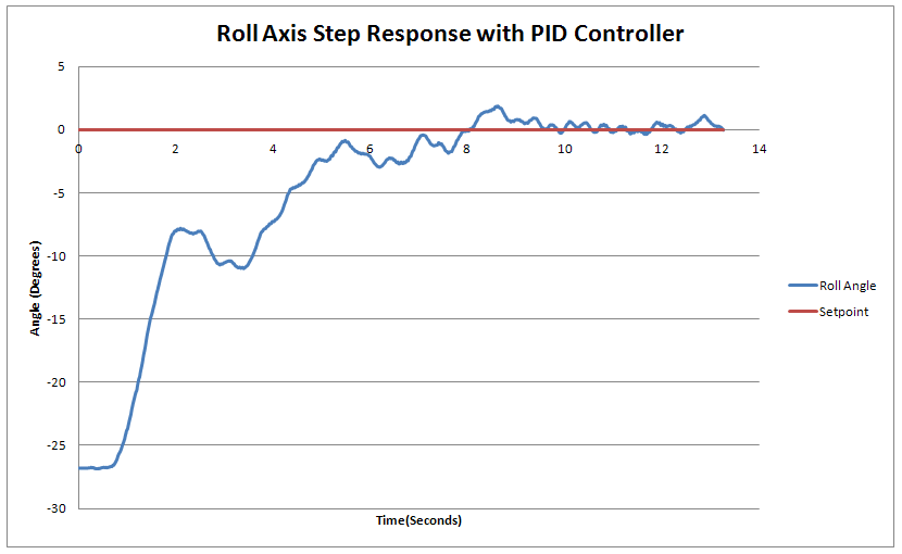
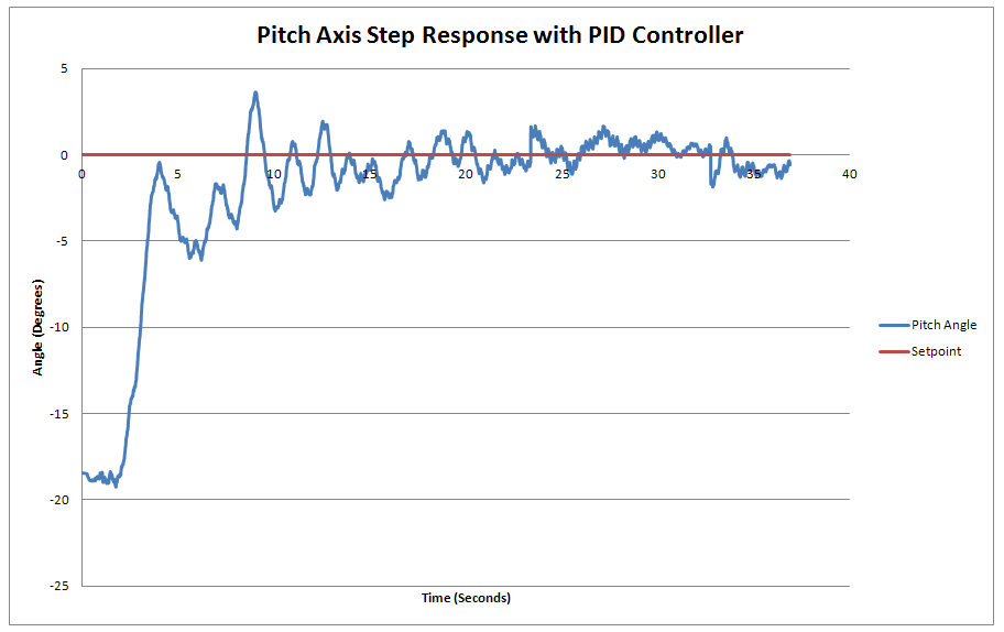
Currently the step responses for my two PID loops look like this:

As you can see there is till a bit of oscillation but I do have both axis’ stable which is the first step. Some of the oscillation I think is die to the fact that the kalman filter cannot track fast movements very well so when the quadcopter is rotating fast there is an inherent lang in the output of the kalman filter. This may or may not be an issue in the quadcopter since these loops are just used to maintain a constant set-point and should never be moving very fast. If I do have problems I think I might be able to improve this by running the kalman filter and sensor sampling at a faster rate than the feedback loop. I might investigate that in the future.

Somethings I have learned in this exloration with implementing PID loops:

There are two was of implementing derivative action in a PID loop; error feedback and rate feedback. In error feedback you take the derivative of the error the same as the integral and proportional parts. With rate feedback you take the derivative of the output and add that to the error and the integral of the error. The advantage of this is you don’t have any effects from a changing setpoint so normally you have less overshoot.

Block diagram for PID feedback loop with derivative on the error
Block Diagram for PID feedback loop with derivative on the output

There is no worng choice between the two but I chose to use rate feedback in my quadcopter. One thing to note with rate feedback is you need a negative Kd or to subtract it from the Integral and Proportional parts else you get positive feedback and an unstable loop. That took me a while to figure out…

A couple important thing I learned about implementing the integrator. The first is to have some sort of anti-windup scheme implemented in your integration. I did it the easiest way by setting a saturation limit on the output of the integrator:

if(I_Value_Pitch >100)
I_Value_Pitch = 100;
else if(I_Value_Pitch<-100)
I_Value_Pitch = -100;

This way the output of the integrator will never go over 100. A wound up integrator can be very dangerous especially when dealing with propellers spinning at thousands of RPM.The second thing is to always reset the integrator when stopping and restarting the PID loop or it will quickly shoot off in one direction the moment you restart it.

Anyway with two stable PID loops next step see if I can get it to fly!

Andrew


Quadcopter Hardware Complete

Now the hardware for my Quadcopter and a good portion of the software is complete for the quadcopter. The hardware really consists of 4 parts: The controller board, the quadcopter XBee board, the USB XBee board and the quadcopter frame with motors and ESCs. The quadcopter XBee board plugs into the top of the quadcopter controller board which is then mounted on the frame. The next part is to get the control loop working and then i should have a working quadcopter.

Here are a few pictures of the hardware to date:

Quadcopter Controller Rev 1

As mentioned before I made a few mistakes on the first revision of the Quadcopter controller board. Although I was able to modify it and get it up and running, I decided to spin another board and do a second revision to fix the things I learned with the first revision.

The changes on this revision include:

  • Change the 5V Regulator (U3) to a TO-220 package LM7805
  • Increase the hole size on the power connection since the wire I used wouldn’t fit.
  • Change the Accelerometers from the Invensense IDG-500 and ISZ-500 analog to the Invensense ITG-3200
  • Change the Gyroscope from the Analog Devices ADXL 335 Anaglog gyroscope to the ADXL 345 Digital gyroscope
  • Since the sensors are digital I was also able to remove the precision voltage reference for the ADC.
  • I also fixed up the footprint on the compass. The newer version of the datasheet for the HMC5883 said that it required that no power traces run underneath the chip and that there in no copper planes underneath so I have removed both.
  • I removed the level shifter on the PWM lines that control the motors since I found that the ESCs would work with 3.3V logic.
  • I also added a few more testpoints and an LED that is controlled by the microcontroller

Once I build up the new boards I will post picture of the new board built up but here is a picture of thelayout an the schematics:


Schematic
Quadcopter Controller R1.0

Andrew

Quadcopter Wireless UART Gateway

Currently I am using a USB to TTL Serial cable to communicate between the computer and the microcontroller. This acts as a tether on the quadcopter and would be much better if it would be wireless to eliminate the leash on the quadcopter. To do this I designed a board that would stack onto to main board plugging into the UART port and would connect the UART port from the microcontroller to a Digi Xbee module like shown below:

These modules offer an easily configuralbe point to point wireless UART gateway. SnceI would need two modules; one on the quadcopter and one connected to the computer I also designed the board to e populated to connect up to a computer’s USB port. To do this I connected the UART port on the Digi module to an FTDI FT232RL USB to Serial chip and have that connect to a male USB A port which can then plug into the computer.

Schematic:
Wireless UART Gateway

Andrew

Quadcopter Construction

As mentioned before there were some modifications that were needed to make the first revision of the quadcopter controller work. I replaced the original 5V regulator with an LM7805 and I removed the level shifter on the PWM and connected the PWM lines up to the headers with wires. I also bought a Sparkfun Electronics breakout board with an Analog Devices ADXL 345 3-axis digital accelerometer and Invensense ITG-3200 3-axis digital Gyroscope, connected them to the I2C bus on the board, and hot glued the breakout board to the main PCB. The modified PCB is shown below:

I also bought a quadcopter frame, motors, ESCs and propellers from Aeroquad.com. Shown below is the assembled quadcopter.

Andrew