Altium CircuitMaker and CircuitStudio

I have used Altium Designer professionally at work for a long time and it is a great too to use. it has it’s quirks like any tool but it is a very powerful EDA tool and I have design many boards with it. It has always been quite expensive and really just reserved to businesses though. I have looked at some of the lower cost tools like Eagle and Diptrace but really don’t have a lot of motivation to learn a new tool for home use.

Recently Altium has come out with two new packages; CircuitMaker and CircuitStudio which are based on the Altium Designer code so they have a lot of the same workflow.

CircuitMaker is a free cloud based tool which is awesome for it’s price, probably the best free EDA tool. It has the same powerful 3D capabilities as the Full Altium Designer, Altium Designer does have some workflow improvements but I realize they do have to differentiate the products somehow. The only problem is it is online only with cloud storage. This makes it slower to access files and libraries as well as you cannot access it without an internet connection which could be a problem for some people. The speed was the biggest problem for me, it took so much longer to create a library part  because it had to load from the cloud server and push it to the cloud server to save, as well as searching for parts was slow. There were a lot of parts in the cloud library but most of the time I didn’t like how the schematic symbol and/or footprint was made so I usually remade them anyway.

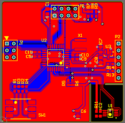
Here is a project that I have made and am waiting for the boards to come in.

https://circuitmaker.com/Projects/Details/Andrew-Swanton-2/Reflow-Oven-Controller

CircuitStuido has all the same features as CircuitStudio but is a standalone tool so it can be used offline and all storage is local. It is a paid tool and it’s not particularly cheap (albeit much lower cost than a full license of Altium Designer) but Altium recently had a promotion for 50% off a license of CircuitStudio which I had to jump on. Creating library parts is not my favorite part of designing a board so to make that experience easier and quicker is worth the cost to me, plus the local storage and less reliance on an internet connection is nice.

I quickly threw together a small board last night to try it out and it works great, the library management is local and much quicker and easier to use.

If you can afford it I would recommend CircuitStudio over CircuitMaker due to the speed of local storage and library management but for the low price of free CircuitMaker is a very powerful tool and wouldn’t have an issue recommending it to anyone.

Andrew

Electric Imp Temperature and Humidity Sensor Followup

This post is a followup from my post here about my Electric Imp based Temperature and Humidity sensor.

I left my sensor my the deck of my apartment starting on January 25, 2015 and it has been running up until September 17, 2016 on the same set of batteries. For the past almost 22 months it has woken up every hour, read the temperature and humidity and posted it to the internet.

This is the temperature data measured by the Silicon labs Si7021 Temperature/Humidity sensor:

temperature-sensor

There may be some erroneous readings as I don’t think the temperature spiked up to 50° C on my balcony but overall the readings usually seemed believable.

Here are the battery voltage measurements over the course of the test:

battery-voltage

There is the occasional spike down where i believe it was a day where the electric imp servers had down-time or the electric imp software had an update where the device was online for longer than expected. One bug I noticed was that if the servers were down it would stay online trying to communicate with the electric imp servers and drain power. To improve this there should be a timeout implemented where if it cant communicate with the servers after a couple seconds it will give up and shut down, but I will be the first to admit I am not the best embedded software developer.

Overall I was impressed with the amount of battery life that I was able to get out of this mostly due to the low sleep current of the electric imp.

Another idea to improve the battery life would be to use a low power timer to cut the power to the WiFi device when sleeping instead of using sleep function of the microcontroller

http://www.ti.com/lit/ds/symlink/tpl5100.pdf

This has a current consumption of 30nA compared to the ~8uA of the electric imp’s sleep mode. Which could be set to periodically wake up the microcontroller and then cut the power so that the sleep/off current is extremely low.

Andrew

Electric Imp Based WIFI Power Switch

My quest for home automation has been slow but I have made some progress. The first thing I wanted to control was some of the lights in my apartment from my phone.

WARNING: This project contains mains power which can be dangerous; beaware this project has not passed any safety compliance testing. I hold no responsibility if anyone tries to reproduce this project

Since I had used the Electric Imp before I designed a board with the electric imp IMP001 module that would switch a relay when sent a command from the internet via my phone. The electric IMP module and relay get power from the mains from an AC/DC converter module from CUI VSK-1S this is a neat little module that takes in 85 to 305Vac and outputs 5V 200mA max power which is more than enough to power this project it’s also UL recognized and is CE compliant. For safety I added a fuse and an MOV to the mains.

WIFI Switch PCB
Electric Imp WIFI Power Switch PCB

I also updated my Android application which I had made to monitor monitor my temperature and humidity sensors to send HTTP requests to the Electric Imp servers when then send the request to my board which  then turns the relay on and off.

Home Control App

I then designed a simple enclosure and 3D printed to finish it off.

WIFI Switch Enclosed

It was a simple project but fun and useful and am looking forward to making more projects to continue automating my apartment. One issue I had with this solution was the cost, the full BOM cost came to around $90. A big part of the cost was the Electric imp module and support circuitry needed for it. One option would be to change to the ESP8266 which is an inexpensive WIFI chip that’s getting really popular but would require a bit more software work since I wouldn’t have the Electric Imp server back-end. But that’s a project for another day.

Schematic Here

Andrew

Electric Imp Temperature and Humidity Sensor

Continuing the project from my last post. I designed a PCB for my Electric Imp sensor but instead of the 10K thermistor I used on the prototype i changed it to use the Silicon Labs Si7021 Temperature and Humidity sensor. This sensor allows me to measure and trend both the temperature and relative humidity with pretty decent accuracy; it’s specced at +/-3%RH (from 0 to 80%) and +/-0.4 °C (from -10 to 80°C). I also added a boost converter from the battery to the electric imp so when the battery voltage gets below the threshold needed for the Wifi to operate (2.5V) it will get boosted to about 2.8V so that I can still use the remaining energy in the batteries.

Electric Imp Temp/Humidity Sensor

From testing I found the boost converter works well but if the battery voltage is too low the startup current of the electric imp will cause the board to brownout before it has time to enable the boost converter. I found this happens at battery voltages less that about 2.2V. Probably adding more low ESR bulk capacitance on the Electric Imp’s supply rail would help with this.

I originally designed it to use an off the shelf case but eventually just decided to 3D print a case for it. I would like to redesign this at some point to make it smaller; it’s pretty bulky right now especially in the case.

Electric Imp Sensor in it's Enclosure
Electric Imp Sensor in it’s Enclosure

I setup the electric imp to wake up once per hour read both the temperature and humidity and post the data to Thingspeak.com. I built two of these sensors and placed one inside my apartment and one out on the deck. To read the sensor data I wrote a small Android app that reads the last sensor reading plus pulls in the graphed data from the last 5 days.

From the bit of testing I have done I expect to get at least a year off two AA batteries but probably much better than that.

(Left) Android App Main Page (Center) Plotted Sensor Data (Right) Plotted Batter Voltage

The schematic for the sensor is located Here:

Wifi Temperature Sensor Schematic

Next I want to build a Wifi power switch and expand this Android app to be able to control things in my apartment using the electric imp platform and after that maybe some wifi controlled LED lights for my workbench.

Andrew

WiFi Temperature Sensor Testing Continued

Continuing from my last post here about my Electric Imp based WiFi temperature sensor.

I left my prototype sensor running for 14 days before it stopped transmitting which isn’t nearly the batter life I want out of this but as I said in my last post I was getting anywhere between 800uA and 2mA of current consumption when it was asleep which was way too high.

Here is a plot of the battery voltage over the 14 days the sensor was running:

BatteryVoltage

To show it was working and because I like to make graphs here is a plot of the temperature readings over the same time period:

Temperature

From the battery voltage graph you can see it drops off very quickly, also you can see all those sharp dips. I’m not sure what was causing that I did add a 1000uF capacitor in parallel with the battery to help with the peak power consumption from the WiFi transceiver but maybe the ESR of my capacitor was too high, I’m not sure.

After the battery died I decided to investigate why the sleep current consumption was so high. After looking into it I found that that all the current consumption was from the buck converter on the Electric Imp development board. Since it is a 3.3V buck converter and my battery voltage is 3V max I didn’t need it anyway. Anyway after I modified the board to bypass the buck converter the current consumption dropped significantly to around 31uA.

CurrentNot quite the 6uA sleep current that the Electric Imp datasheet quotes but much better. Even through there is no power going into the buck regulator’s input anymore there might be some leakage currents through the output and/or feedback pin. This current consumption would probably drop if i removed the chip altogether.

Picture of board with buck regulator bypassed:

WifiSensor2

With this change I have only had it running for 24 hours so far but the batter voltage looks a lot better and I’m thinking I should get much better battery life out of this.

BatteryVoltage2

Well I am going to leave it running and see how things go. Next step is to design a permanent board for the WiFi sensor with a boost regulator so I can get all the power out of my batteries.

Andrew


AC and DC Dummy Load

I wanted a variable load for 24VAC that would go up to at least 12VA. Before I would connected power resistors in series but that gets troublesome when you want to change the load with a fine resolution. There are variable power resistors or rheostats but they are big and clumsy and from what I can tell expensive. So I decided to design a little variable AC load that would simulate a resistive load and that would also work with DC. After a bit of work and one board spin I came up with this:

AC Load


Load Circuit

It works like the standard DC load that you can find all over the web with an op-amp that drives an N-Channel MOSFET with a current sense resistor but on this one I added a P-Channel MOSFET in series. This way during the positive half of the AC waveform the body diode of the  P-Channel MOSFET conducts and the  N-Channel MOSFET provides the load and then during the neagtive half of the AC waveform the  the body diode of the  N-Channel MOSFET conducts and the  P-Channel MOSFET provides the load.

To turn of the MOSFETs the op-amp needs to drive the N-Channel FETs gate positive and the P-Channel FETs gate negative so I added a simple +/- 10V supply. First I bring in power through USB just because that is a simple and easy was to get 5V, also I thought I might redesign this with a micro-controller at some point that will be able to do more complex loads. The 5V is fed into a voltage doubling charge pump and then that is fed into an inverting charge pump.

When the voltage to be loaded is connected to the device it is divided by R1 and the potentiometer R3 which provides the set-point for the control loop this makes the load dependent on the voltage which means this simulates a resistive load unlike most DC loads which are constant current loads.

Op-AmpSupply


I had a few issues with this design to begin with:

  • First originally I had one gate resistor that was shared between both mosfets but I was getting some very high frequency oscillations when ever the N-Channel FET turned on, isolating the MOSFETs with separate gate resistors solved that issue.
  • Next I had trouble getting the control loop stable; originally I used the jellybean part TS321 for the op-amp but no matter what combination of gate drive resistor and compensation capacitor I couldn’t get it stable. I changed the op-amp to the fancier LM7321 which is a higher current output and unlimited capacitive load op-amp and with that I got the control loop stable.

One thing I would do if I do another revision of this design would be to add more protection. I have damaged it a few times by connecting the load power without connecting the 5V.

Full Schematic:

Variable AC-DC Load

Anyway this was a fun little project that I wanted to share :)

Andrew

Wifi Temperature Sensor Testing

Electric Imp CurrentLike I said in my last post I’ve decided to rethink my wireless temperature sensor. Instead of using a local wireless protocol like ZigBee or the Nordic Semiconductor 2.4GHz wireless. I want to investigate using WiFi instead. After doing a bit or research I found the Electric Imp WiFi modules (Electric Imp) look like they might be a good fit. They should have a low sleep current (<10uA) and seem to have a lot of support for the software side which is where I usually am lacking in my projects; I’m fine designing hardware but get frustrated with software development easy.

With some very quick back of the napkin calculations I figure that I can have one Electric Imp Running off 2 x AA batteries that logs the temperature and sends it out to the internet every hour and have it last at least a year on one set of batteries. Yesterday I bought and Electric Imp IMP001 module and a breakout board. I powered it with 2 x AA batteries in series and set it up to log the temperature of a thermistor and the battery voltage. With a  little bit of code I have it sending the readings out to Xively; I used them when they were called Cosm on a previous post.

Electric Imp Test

Here are the live feeds from Xivley for the past 24 hours for both the thermistor temperature and battery voltage (Sorry to all future readers if these go down eventually)

Now this isn’t a perfect test since the Wifi on the Electric Imp module with cut out when the voltage reaches 2.5V or about 1.25V per cell and Alkaline AA batteries are fully drained when they get to 0.8V per cell. So at some point I will need to design a board with a boot converter so I can utilize the full capacity of my batteries.

I did some testing last night to measure the current draw of the Imp module and found that my sleep current was a bit higher than what is specified in the datasheet; I was getting around 800uA but that’s most likely I have it setup wring and not going to sleep fully. I did make sure that I am controlling the thermistor properly which a GPIO pin so that isn’t wasting current when the device is asleep. I also measured the current when it wakes up and transmits.

Electric Imp Current


This was measured through a 10 ohm resistor so we have a peak current of about 130mA and an average current for the whole transmit pulse of about 50mA for 75ms. So that’s not bad as long as it’s not waking up very often I should get pretty decent battery life. I think when I have the whole thing setup I will probably have it text or e-mail me when the batteries get low.

Going forward on this project I think I am going to have to get another electric imp module so I can do some more development while I leave this one running and I will work on my own board with a boost converter and maybe some other sensors to connect to the Imp.

Andrew

Wireless Temperature Sensor Rev 1.0

Well in the past I had talked about wanting to do a big home automation project and to start with that I wanted to design a battery powered wireless sensor node that I could place around my apartment. The first iteration of this design was posted here https://andrewswanton.com/?p=780 but I had problems with the PIC24 microcontroller I designed in to that one.

I have been wanting to get some experience programming Atmel AVRs since they seem to be very popular and look like very nice little 8-bit microcontrollers. I took the same basic design of the last revision and replaced the microcontroller with the Atmel ATmega168. Since these are very popular microcontrollers so I figured there would be a lot of libraries already done to me getting it up and running quicker. Although, this microcontroller doesn’t have all the fancy low power features of the low power series PIC24 used in the last version but I figure that I get get the power consumption down by having it sleep most of the time and then just quickly wake up every once and a while to read the temperature sensor and then transmit.

Here is picture of the populated board with the NRF24L01 wireless module.

Sensor Rev 1 Layout

DSC00506

Layout:

DSC00506


Schematic:

Wireless Temperature Sensor Rev 1_0

Now I actually designed this a while ago and am just getting around to posting about it now. Since designing this board I have been thinking about the whole system design and am thinking about taking a different approach. Instead of having this local network of sensors that talk to a main “server” in my apartment why not jump on the “Internet of Things” bandwagon that everyone else is doing and make it Wifi enabled. This eliminates having to deign a support the local server portion of the system and I could have the devices talk to some sort of “cloud” service. Anyway it’s just an idea and I will post more about it in the future and if it doesn’t work out I can always come back to this design.

Andrew

Makerfarm Prusa 8″ I3

I have always wanted my own CNC mill but they can be very noisy and messy and since I live in a 1 bedroom apartment I thought buying one wouldn’t be the best Idea, at least until I move into a house :). So I thought the next best thing would be a 3D printer, they are very popular now and you can get RepRap kits for very reasonable prices.

I did some research and decided on the Prusa I3 kit from Makerfarm.com. The kit came quickly and assembly was relatively painless and took a couple evenings. Overall I am happy with the kit I feel it is good value for the money but I might do a more detailed review of the kit later.

Prusa I3


After some tuning of the machine and tweaking parameters in Slic3r I am able to get some pretty decent results. Right now I am using Black PLA for my filament but I will probably try ABS when I need to buy more plastic.

Surface Finish

So far I have made a few useful things. Here is the solder spool holder I designed in Solidworks and printed with my 3D printer, it turned out pretty good, a little rough around the edges.

Solder Spool Holder

Here is a pencil/tool holder for my work bench, the surface finish is a bit bumpy so I might have to do a but more tuning but overall came out well.

Tool Holder

Here is a quick video of it printing my solder spool holder

There are a few improvements I want to make to the machine. I want to make a better spool holder for the plastic filament, right now I have something thrown together with leftover pieces from my quadcopter stand. I want to do a better job of the wire management, right now the wires are just zap strapped together so it’s not a total rats nest of wires but I know I can do a better job if I sped some time on it. I also want to get a raspberry Pi and use that as a print server to run it and store the G-Code files; right now I have to slice the files on my laptop, transfer the files to an SD card and then plug the SD card in the machine and print. My idea is to have a Raspberry PI with a WiFi dongle plugged into the RepRap controller and have it running Pronterface of Octoprint and transfer files through FTP over WiFi. I’ll do a blog post about that when I get that all setup.

Anyway that’s all for now.

Andrew

Engineer in Training

I haven’t posted in a while but thought I would give a quick update recently I received notice from APEGBC that my application was successful and I am now officially an Engineer in Training. This is the start of the next phase in my career where I work towards getting my Professional Engineer (P.Eng) designation. This involves doing 4 years of work experience under supervision of a P.Eng and keeping track of my work experience over those four years. I will also need to take a Law and Ethics seminar and a Professional Practice exam but I will take those at a later date.

Anyways as far as projects I’m working on are concerned I recently bought a rep rap 3D printer kit and have been playing with that.I will do a separate blog post about that.

Andrew