Quadcopter Controller Rev 0 Revised

Well I eventually got the PCBs back from being made and built it up. I then powered up the board and there was smoke…..

Turns out I made a mistake choosing the 5V regulator. It turns out he one I used Microchip MCP1826S has a max input voltage of 6V and I tried to power it with 12V…oops.  But I can replace it with the good old LM7805 which I had laying around. Afterwards I noticed that even if the MCP1826S would accept a 12V input, with the power dissipation of a linear regulator stepping down 12V to 5V it would have gotten very hot possibly overheated. This is shown below.

Since the input is 12V and the out put is 5V that means there is 7V across the pass transistor of the linear regulator. According to the datasheeet for the MCP1826S the thermal resistance of the junction temperature to ambient temperature for the SOT223 package is 62°C/W

The max curent of the circuit should be about 110mA so:

LDO Temperture CalculationSo using the Thermal Resistance from the LDO datasheet of 62°C/W I get a junction temperature of 70.74°C which is hot but not enough to over-heat the chip but the 62°C/W was assuming a 4 layer PCB which wold be more thermally dissipative than my 2 layer PCB so the actual temperature will be higher than 70.74°C, Also it will heat up the PCB which could affect the sensor accuracy since they drift with changes is die temperature. To be safe on the next revision of the board I will use the LM7805 in a TO-220 package which has a much lower Ambient to unction Thermal Resistance and it is a through hole part so it will not heat up the PCB as much.

There were other problems with this revision that will have to be cleared up on the next revision:

  • I used a level shifter on the PWM output to shift the 3.3V PWM from the microcontroller to 5V since I read in some forums that some ESCs do not work with 3.3V logic. The only problem is it turns out the level shifter I chose only works with voltages 3.3V and lower…oops guess I need to double check the datasheets before I send these things off. Luckily the ESCs I have work with 3.3V so I can mod these boards to work.
  • I wasn’t too happy with the noise performance of the analog sensors the output of the Kalman filter was still bouncing around 1-3 degrees when the system was at rest. I bought a breakout board from Sparkfun with a digital accelerometer and digital gyroscope and got much better results. Changing to a digital sensors also allos me to use 1 3-axis gyroscope chip and I can remove some other parts like the analog reference. The noise performance is shown in the graphs below:

Andrew


Quadcopter Controller Design Rev 0

Now that I have a microcontroler I can desgin the rest of the controller. For the sensors I chose to use:

  • X and Y axis Gyroscope: Invensense IDG-500
  • Z axis Gyroscope: Invensense ISZ-500
  • 3 axis Accelerometer: Analog Devices ADXL335
  • Pressure Sensor: Bosch BMP085
  • Compass: Honeywell HMC5883


The Accelerometer and Gyroscopes will be used to control the rotational axis’. I chose to use analog snsors to beable to have the fastest update rate. Had I used I2C digital sensors the max possible update rate would be much slower since the ACD conversion time i significantly less than the time it takes to read data from an I2C sensor at their max baudrate of 400kHz. Thee are some downsides I am going to have to live with since I am using the analog sensors I need to have a stable and accurate volatge reference for the ADC, in whch I chose the:

National Semiconductor LM4132EMF-3.3

  • 0.5% Tolerance
  • 30ppm/°C  Temperature Coefficient
  • 50ppm Long Term Stability

Other downsides are to the anaog sensors are the 10bit ADC on the micro controller, which only gives 1024 counts which could be a problem. Also Analog sensors are going to be more suceptable to EMI which cold be thrown off from the brushless motors. Even though the downsides I finished the design with the analog sensors and sent the Gerber files off for the boards to be made.

Schematic:
Quadcopter Controller Rev 0

Quadcopter Controller Rev 0

Andrew


Quadcopter Microcontroller Selection Cont.

I also did another test to compare the speed of the two chips. I wrote the Kalman filter code that I will use in the quadcopter and ran it in MPLABSIM for the PIC32 and DsPIC both running at 80Mhz. I go he following results:

Kalman FIlter Simulated on DsPIC
Kalman Filter Simulated on DsPIC
Kalman FIlter Simulated on PIC32
Kalman Filter Simulated on PIC32

As you can see from the Stopwatch column the PIC32 uses less than half the instruction cycles for the same code of the DsPIC. Also the PIC32 ran the same code 5 times faster than the DsPIC. Speed can be important if I want to have high update rates on the PID loop so from all this I chose to use the PIC32 on my quadcopter controller.

Andrew


Quadcopter Microcontroller Slection

The controller for the quadcopter is the brains of the operation. The first part of the design is to choose a microcontroller. Since I am most familiar with the Microchip IDE and I already own the microchip Tools.

I chose two candidates from Microchip:

Device Flash Memory RAM Timers Output Compare ADC UART I2C
dsPIC33FJ256GP710A 256KB 30KB 9 8 12 bit 2 2
PIC32MX795F512L 512KB Program + 12KB Bootloader 128KB 5 5 10 bit 6 4

Comparing the two:

  • Flash Memory: The PIC32 wins here 512KB vs 256KB, I may or maynot need the extra memory but since I am more of a hardware guy than a software guy it wont hurt to have extra memory.
  • RAM: The PIC32 here wins again 128KB vs 30KB, this could be important because I could use the RAM to log data on the PIC32 on the DsPIC I would probably have to use external serial memory such as FRAM which is expensive and the transfer rate would be much slower than the on-board RAM.
  • Timers: This is bascally a tie although the DsPIC has more Timers I probably only need 2: 1 for the PID loop and 1 for the PWM.
  • Output Compare: This is bascally a tie although the DsPIC has more Output Compare Channels, I only need 4: 1 for each motor.
  • ADC: The DsPIC wins here hands down a 12bit ADC gives you 4 times the resolution
  • UART: This is bascally a tie although the PIC32 has more UART Channels, I only need 1
  • I2C: This is bascally a tie although the PIC32 has more I2C Channels, I only need 1 or 2

Continued on next post.

Andrew

Quadcopter Overview

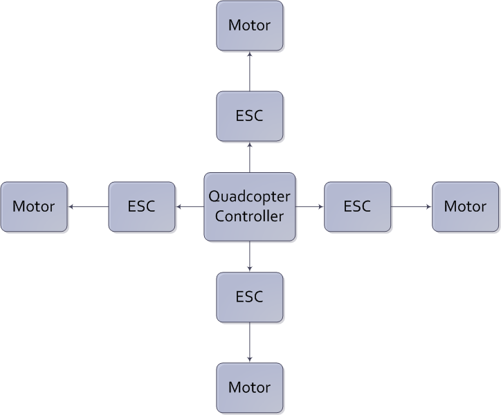
For my final project for the BCIT Bachelors of in Electronics I am building a Quadcopter. This is a project I have been working on or the past few months and have decided to start documenting it. Below is a simple block diagram of the major components of the Quadcopter:

Quadcopter Block Diagram

It consists of:

  • A Quadcopter Controller which will be a custom PCB that I will design
  • 4 Electronic Speed Controllers which are brush-less motor drivers to interface between the Quadcopter Controller and the brush-less motors, which will be purchased
  • 4 Brush-less Motors which will be purchased

The main goal of this project is to get one axis of the quadcopter to work stably under feedback. Ultimately I would like the Quadcopter to hover or fly stably.

Andrew